|
Basic Image AlgorithmS Library
2.8.0
|
|
Basic Image AlgorithmS Library
2.8.0
|
A central concept in BIAS is the projection matrix, which represents the image creation process in the pinhole camera model.
The pinhole camera projection is a linear mapping of 3D world points to 2D image points. For this to be linear, world points and image points need to be represented in homogeneous space, i.e. the BIAS::PMatrix is a 3x4 matrix mapping 4-vectors of IP3 (BIAS::HomgPoint3D) to 3-vectors of IP2 (BIAS::HomgPoint2D). Usually a PMatrix is made up from a Rotation, a Center and a Calibration. The concept of constructing the 3D points from 2D measurements is called Triangulation. The generated 3D points (as well as 2D points) usually have some uncertainty regions, which can be modelled using quadrics and conics and covariance matrices.
Each real world pinhole camera is modeled by several external (location C, orientation R) and internal parameters (focal length, aspect ratio, ..., held in the KMatrix, which is also called the calibration) parameters, which alltogether encode the PMatrix like:
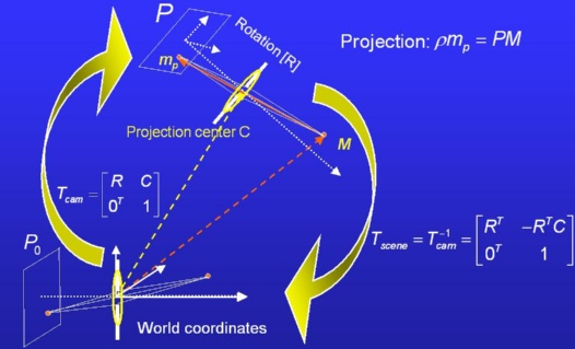
P = K [ R^T | -R^T * C ]
If we know K, R, C of a camera we can compute the PMatrix used for projection. The other way around, if we have such a P we can decompose it into K, R and C. Such matrices are called metric. However, our PMatrix may also be an estimate made up from noisy measurements maybe in a projectively skewed space. Then this matrix cannot be decomposed into BIAS::KMatrix K, BIAS::RMatrix R, and BIAS::Vector3 C. The IsMetric flag of BIAS::PMatrix determines if we have a "real" (or metric) or "projective" PMatrix (when writing as XML, this leads to different output) . Once a PMatrix is decomposed, the decomposition (K, R, C) is stored in the object and returned at the next call of decompose without re-computation. This is the main difference to the base class BIAS::PMatrixBase, which does not know anything about decomposition. The caching saves cpu time but the user is now responsible for indicating that the matrix has changed and that cached decomposition is invalid. If BIAS_DEBUG is defined, it is checked whether the PMatrix has been corrupted since the last decomposition and if so the program aborts with a warning message. In "Release" mode a corruption is not detrrected any more and you will simply get wrong results if you change the matrix without notification.
There are several ways to represent the internal and external parameters, instead of decomposing to K,R,C one may also decompose to K and A,H,V,C, where A (optical axis), H(vector parallel to image line) and V(up-vector of the camera) are actually the columns of R or the rows of R^T. Furthermore we can now encode the internal parameters like focal length, aspect ratio, skew and principle point into these unit vectors and end up with another decomposition of P, which is A0, H0, V0 and C.
PMatrices can easily be visualized using ThreeDOut. The class BIAS::PMatrixEstimation can compute two PMatrices consistent with a fundamental matrix (BIAS::FMatrix) or an essential matrix (BIAS::EMatrix), while BIAS::PMatrixLinear will compute a PMatrix given enough 2D/3D correspondences.
The relationship of two views with different camera centers (two projections matrices) is represented by the fundamental matrix F, a 3x3 matrix with rank 2. Perfect correspondences x1 in image 1 and x2 in image2 fulfill the contraint x1 * F * x2 = 0. F * x2 gives the homogeneous representation of the epipolar line of x2 in image 1, where F is an object of class BIAS::FMatrix. If the calibration of the cameras is removed from the fundamental matrix, we get an essential matrix, represented by BIAS::EMatrix, which does only hold the relative poses of the two cameras. Parametrizations of these classes (sometimes needed for optimization) can be found in BIAS::Parametrization. The same concept as the fundamental matrix, but between three views is encoded in the class BIAS::TFTensor, the trifocal tensor representation.
The directory Geometry hold several classes for linear/least squares (non-robust) estimation of all these objects, see for instance BIAS::FMatrixEstimation.
Rotations in IR^3 around the origin can be done using a 3 by 3 rotation matrix (BIAS::RMatrix). Another possible representation is the very intuitive axis angle representation, which can be calculated from a rotation matrix (BIAS::RMatrix::GetRotationAxisAngle()) and be transformed into a rotation matrix (BIAS::RMatrix::SetFromAxisAngle()). Quaternions (BIAS::Quaternion) have also proven to be suitable for representing and performing rotations. They come with a special algebra. They improve the number of needed components for estimation, suffer from no gimbal lock problem and are more efficient performing rotations. A 4D quaternion can be interpreted similar to the axis angle representation, where the so called imaginary part contains the axis direction, and the real part is the cosine of the half rotation angle. Please observe that in the representation chosen in BIAS the real component is the last (or fourth) component!
The BIAS::KMatrix as a 3x3 matrix describes a transformation in/of the image plane. In the context of the projection matrix it encodes the internal camera parameters such as focal length, aspect ratio, skew and principle point. In this context it is an upper right triangular matrix.
Given two cameras (and their PMatrices P1, P2) and an image point x1,x2 in each of these cameras, which refer to the same (unknown) point X in 3D space, we can compute this point X by backprojecting the image points and intersecting the two projection rays. This is performed by BIAS::Triangulation. For noisy measurements x1,x2 and/or P1,P2 the rays wont intersect exactly, but there are several techniques to determine a good (regarding some measure) 3D point in that case. Additional to the triangulation we can compute an uncertainty measure of the estimated 3D point, which depends on the intersection angle of the rays. This measure is modelled as a gaussian probability distribution with a 3 by 3 covariance matrix (BIAS::CovMatrix3x3). See also ExampleTriangulate.cpp
In the meanwhile the number of supported camera models in BIAS have grown. Some of them like for instance spherical cameras come with the need of sever changes in the camera model. In order to provide a generic and polymorphic structure the BIAS::Projection and the BIAS::ProjectionParametersBase hierarchy was created. Although still only single center of projection models are covered, the non linearities of radial/tangential distortion, the fish-eye camera model, spherical and cylindrical cameras can be addressed. Also a convenient modelling of camera rigs is made possible. This is achieved by seperating intrinsic and extrinsic parameters. It is assumed that extrinsic parameters beeing mere 3D affine transformations are shared by all camera models, hence they are contained in BIAS::ProjectionParametersBase, the intrinsic parameters are implemented in the respective classes derived from BIAS::ProjectionParametersBase like BIAS::ProjectionParametersPerspective and BIAS::ProjectionParametersSpherical. This hierarchical structure allows to implement algorithms using "projections" and "unprojections" without bother with the actual camera model. This for instance makes a very convenient implemention of undistortions and rectification possible, like presented in the BIASImage library.
In the class hierarchy induced by BIAS::CoordinateTransform3D a concept for dealing with relative affine coordinate frames is implemented. The basic idea of affine coordinates is their interpretation by means of an affine sum of a predefined base of vectors. Observe that the precise definition of coordinates for the basevectors already requires some sort of base, which per se is the euclidian standard base. This standard base is named the global frame while the coordinate frame, which shall be defined is named the local base. In other words the local frame is dependent on the global frame. This is also sometimes expressed as the local frame beeing defined relative to the global frame. This mechanism easily allows to model relations between camera frames, like needed for camera rigs. Not clear? Think about the world and camera coordinate frames occuring with the pinhole camera model: which is the global and which is the local frame? Ok and now assume you have two cameras CamA and CamB. If you would like to express CamB relative to CamA, you would try to find the basevectors for CamB relative to the basevectors already defining CamA. Consequently you would render CamA to be the euclidian standard base and hence the global frame. CamB would then become the local frame. BIAS::CoordinateTransform3D provides methods to generate this global/local relations between coordinate frames from different input configurations (like the two cameras CamA and CamB, mentioned before).
A quadric Q is a surface in 3D (e.g. an ellipsoid) described by an implicit quadratic equation in IP^3 (x^T * Q * x = 0), while a conic C is a contour line in 2D (actually a cone/plane intersection, like an ellipse) described by an implicit quadratic equation in IP^2 (x^T * C * x = 0). BIAS::Quadric3D is a 4x4 matrix, while BIAS::Conic2D C is a 3x3 matrix. Both entities are the same concept in different dimensions. Evaluating the above implicit equations, it is simple to check if the BIAS::HomgPoint2D (resp. 3D) x lies inside/on/outside the conic(resp. quadric) by evaluating the result's sign. Conics and quadrics are closely related to gaussian normal distributions (they actually encode iso-probability levels), e.g. BIAS::Quadric3D can easily be constructed from CovMatrix3x3, which represents a covariance matrix of a normal distribution. It is worth to know that pinhole cameras map quadrics to conics. See also ExampleConic.cpp
 1.8.5
1.8.5

